
Insulating flange Type 61 – CE-compliant electrical isolation for KKS systems
CE-compliant insulating flange connection for the safe electrical isolation of flange connections and KKS systems.
CE-compliant in accordance with 2014/68/EU
Bearing the CE marking and compliant with the Pressure Equipment Directive 2014/68/EU.
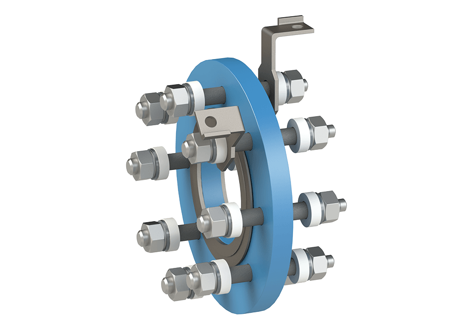
CE-compliant Type 61 insulating flange for electrical isolation in cathodic protection systems
The Type 61 insulating flange connection is used as an electrical safety measure to reliably interrupt the metallic conductivity of a flange connection or a cathodic protection system. It also provides protection against bimetallic corrosion.
A key feature of Type 61 is its CE conformity in accordance with the Pressure Equipment Directive 2014/68/EU. Marking is provided via a UV-resistant type plate; the relevant declaration of conformity forms part of the documentation.
Type 61 is intended for gases in accordance with DVGW Worksheet G 260, non-aggressive gases and non-aggressive liquids. For aggressive gases and liquids, a specially coated version, Type 61A, is available. Further variants allow adaptation to different installation situations.
CE-compliant in accordance with 2014/68/EU
With CE marking and declaration of conformity.
Electrical KKS isolation
Interrupts metallic conductivity.
Combinable versions
Types 61, 61D, 61L, 61S and 61A.
Protection against short-circuiting
Type 61D with an outer diameter 60 mm larger.
No special maintenance required
Operator checks remain necessary.
Limit values per version
Pressure and temperature as per type plate.
Advantages and versions of the Type 61 insulating flange
Combinable variants to suit the installation situation
Defined scope of supply for the connection
No special maintenance required on the component
Flexibly adaptable to your requirements
The Type 61 Insulating flange is available in different versions to optimally respond to different operating conditions.

Insulating flange Type 61

Insulating flange Type 61D

Insulating flange Type 61S

Insulating flange Type 61A
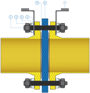
Design and operation of the Type 61 insulating flange connection
The Type 61 insulating flange connection consists of coordinated metallic and insulating components. When fitted, the insulating ring and insulating washers interrupt the metallic conductivity of the flange connection, thereby enabling electrical isolation within a KKS system
Component overview:
- Screw bolt – 25CrMo4 (with polyolefin coating)
- Nut – 25CrMo4
- Washer
- Insulating disc
- Comb profile seal
- Insulating ring
- Cable lug
The fittings are not included in the scope of delivery.
Insulating ring, seals and flange bolting assembly
The assembly comprises an insulating ring, insulating washers, bolts and nuts, flat washers, two comb-profile seals and two cable clamps. The operating instructions specify 25CrMo4 for bolts and nuts, and 1.4571 / graphite for the comb-profile seals. The coated washers have a hardness of at least 200 HV.
The insulating ring and the insulating washers form the insulating components within the flange connection. The pressure, temperature and torque limits applicable to the specific version can be found on the relevant type plate.
How the Type 61 insulating flange connection works
When installed, Type 61 serves to interrupt the metallic conductivity of the flange connection and thereby establish electrical isolation within a KKS system. At the same time, the connection is designed to provide protection against bimetallic corrosion.
Two cable clamps are provided for the integration of an Ex-isolation spark gap. These are fitted to different bolts as standard; if they are to be fitted to a single bolt, this must be specified at the time of ordering. The Ex-isolation spark gap must be fitted in accordance with the manufacturer’s instructions and tested on site after installation. The insulated flange connection must be installed in a manner that protects it from splash water and rain.
Scope of supply for the Type 61 insulating flange connection
The Type 61 insulating flange connection is supplied with the insulating, sealing and fastening components required for the connection.
Insulating ring with type plate
Insulating washers
Screw bolts and nuts according to DIN/ASME
Coated washers
2 comb profile seals
Cable lug for Ex spark gap
Acceptance test certificate 3.1 in accordance with DIN EN 10204
Declaration of conformity in accordance with PED/DGRL 2014/68/EU


Technical specifications of the insulating flange
The Type 61 insulating flange has been tested in accordance with current standards and is suitable for use in gas and pipework systems. The key technical specifications are listed here – the full data sheet is available for download.
Other nominal diameters available on request!





The W2 Type 61 insulating flange in practice
The Type 61 insulating flange is already being used successfully in industrial and gas pipelines. Numerous customers rely on its proven safety, simple installation and long-lasting insulation – even under demanding operating conditions.
Technical specification and enquiry regarding Type 61 insulating flange
The medium, nominal diameter, pressure rating, operating temperature and installation configuration are particularly relevant when selecting the appropriate version. If necessary, please also specify whether a version is required to prevent unwanted bridging, for special flanges, for corrosive media or with a specific arrangement of the cable clamps.